Written by Jay
As a Software Guy ™ I tend to be way more comfortable reversing a binary than following the tracks on a chip and it’s for that very reason that I decided to document the process of hacking home routers the hardware way. The end goal, as always, is and see what kind of access can be gained and ideally get access to some kind of shell with root privileges. Where possible, i’ve tried to not turn to online resources as this is more a learning exercise than any serious research. One cool thing I discovered is that the Raspberry Pi can interface with TTL devices using the GPIO pins meaning I didnt have to purchase any extra equipment for this. TTL is the serial interface used by a lot of embedded devices and consists of four pins - Transmit, Receive, Power and Ground (or Tx, Rx, Vcc and Gnd) and requires either a USB to TTL breakout cable, Bus Pirate (Raspberry Pi!) etc.
Equipment
- Multimeter
- Bus pirate, TTL to USB, Raspberry Pi etc
Targets
- Neatgear DG834GT
- Sky DSL-2640S
Hacking
The obvious first step is to take the router apart and to take a look at what’s going on inside. Once disassembled, we’ll hopefully be able to identify debug ports and use these to gain access to something interesting. Luckily for us, these two routers provide fairly easy access to their serial ports; the Netgear requires only a small amount of soldering to add some headers whereas Sky has kindly shipped the router with the headers provided. The first question is, how do we identify these ports…
Identifying potential pinouts
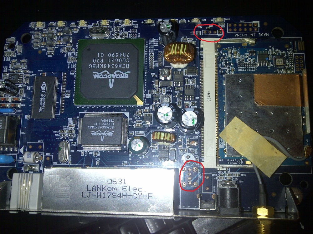
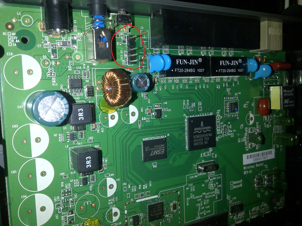
Anyone with even a little experience in this sort of hacking knows that to interface with the serial port on a router, we usually look for a set of four pins (remember Tx, Rx, Vcc and Gnd?). These are easy to notice on the Sky router as the row of five pins with four pins exposed. The Netgear requires a little more eyeballing and there are two likely candidates; one near the top of the board and one near the bottom. In this case, I decided the one near the bottom of the board was more likely as it was also next to another port that looked suspiciously like a JTAG port. Another reason I dismissed the one near the top of the board is because it had what looked to be points for mounting some kind of connector (which i’ve since found out is for USB). You’ll usually find just headers connected to debug serial ports which won’t require mount points.
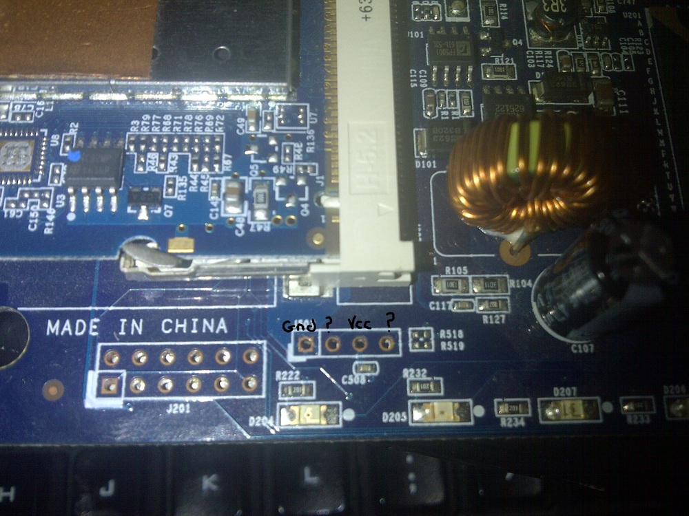
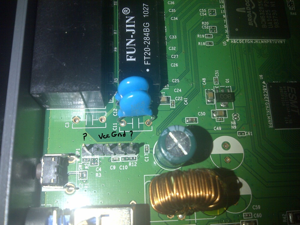
Now we have our suspected ports, how do we identify the correct pins? We know what the four pins do, but not necessarily the order they’ll be in. Time to bust out our trusty multimeter. Lets first identify the ground pin as that’s the easiest. With the multimeter in continuity mode we can detect when a circuit is complete. Place one probe to what we know to be ground and the other to each pin we want to check. To find a known ground I usually use either a bit of exposed metal casing or the ground pin of the power adapter. Remember to keep the device powered off and unplugged when testing! There is less than 1 amp going through this device but we really don’t want to fry anything. When we hear our multimeter sing, or more accuracy emit a continuous tone, we know we have found our ground pin. The second pin to try and identify is the Vcc aka power pin. This pin isn’t necessary to communicate with the device, but by identifying it we only have two pins left which will be Tx and Rx. To identify the Vcc, place one probe on the ground pin we found and test the others in turn. When we hit Vcc, we should hear a very quick beep. This is due to a capacitor that will be between ground and Vcc. Once the capacitor is charged, its resistance will increase. Hence, the quick beep.
Now we only have two more pins to go. The correct way to do this is to attach a logic analyser or oscilloscope to the pins and look at the data coming out but honestly, I just guess. 50% chance of getting it correct after all.
Identifying Power and Ground
The final step is to check the voltage across the pins. Power up the router and use a multimeter to check the voltage between ground and each pin in turn. If each pin measures around 3.3V, it’s likely the device uses TTL and we can take to solder connectors if needed. This was only necessary on the Netgear as the DLink already had them in place.
Connect this to your computer as per your preference (as mentioned, I connected mine to a Raspberry Pi, then connected to the Pi from my PC using SSH), set the correct baudrate etc (in these cases 115200, 8n1), power up the device and (assuming you have Rx and Tx the right way round) BOOM, shell :)
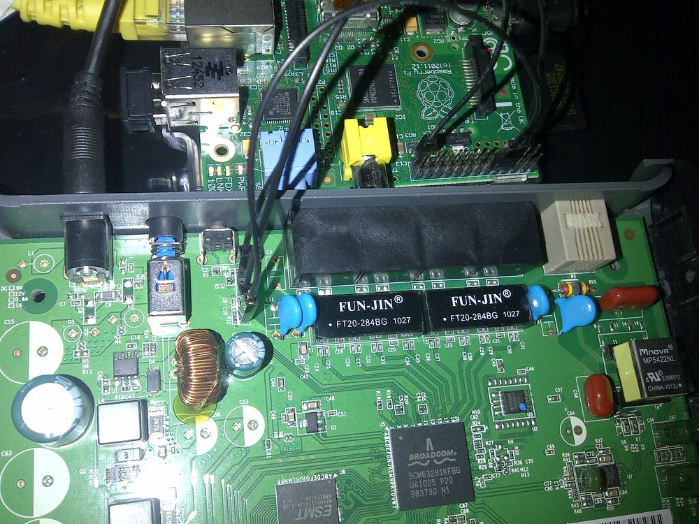
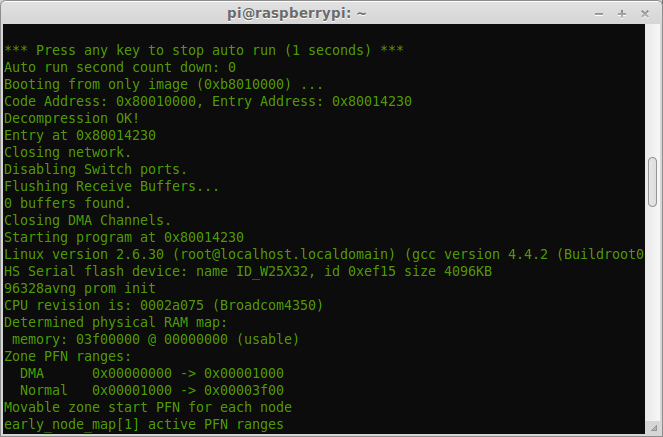
Getting a shell
One interesting thing I noticed is that the netgear won’t drop you straight into a shell. With Rx and Tx connected, all I got was a little garbage on the screen and a little blinking light on the device. This was fixed by only connectng Rx when the device started booting and I was able to interact with the device to get a shell. This did mean that I was not able to access the bootloader though. By changing the setting to 7N1, I was able to view the full startup process, with most of the bootloader text decoded correctly, but in this case I was not able to issue commands. I’m still trying to understand what this means, but my guess is that once the boot loader is complete, the serial settings change. I’ve seen a few devices do this, so maybe a security feature?
Incidentally, the correct pinout is:
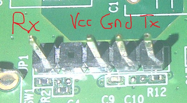
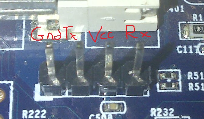
Identifying pinouts
I’ll document any interesting findings in other posts.
Happy Hacking.